
2. Ship Detailed Settings
With Hafenskipper Version 2 you can configure many characteristics of the ship models. Match the models to a specific ship or experiment and understand the influence of the characteristics on the ship behavior. The following settings are available:
| Unit | Parameter | Unit |
|---|---|---|
| 2.1 Power | Single engine power | kW |
| 2.2 Mass | Mass of the ship | Kg |
| 2.3 Engine Type | Engine types selectable are depending on ship: Outboard, single or twin engine Stationary shaft, single or twin engine Sail drive | |
| 2.4 Rudder | Number of rudders | |
| 2.5 Propeller Rotation | Right hand / Left handTwin engine: inwards / outwards | |
| 2.6 Prop Walk | Strength of propeller walk | % |
| 2.7 Rudder Size | Increased rudder size means greater rudder forces. This parameter only influences the rudder force due to the speed through the water. | % |
| 2.8 Prop Wash | Strength of the rudder forces due to propeller wash. | % |
| 2.9 Max. Rudder Angle | Maximum rudder deflection angle to left and to right side. | ° |
| 2.10 Steering Wheel Translation | Translation between steering wheel and rudder angle. | 1 |
| 2.11 Moment of Inertia (Yaw) | Kg * m² | |
| 2.12 Power Bow Thruster | kW | |
| 2.13 Wind Resistance | Resistance of the ship to cross winds. Resistance to head wind is changed in relation. | % |
| 2.14 Wind Center of Effort | Longitudinal offset of the side wind center of effort. | m |
| 2.15 Size of Lateral plan | Size of the lateral projection of the underwater ship. | % |
| 2.16 Center of Lateral Resistance | Longitudinal offset | m |
When percent (%) is stated as the unit, the parameter is set relative to the standard value for each individual ship. In the following you can find an explanation of all parameters in detail:
2.1 Power
This parameter sets the main engine power. With a twin-engine ship this is the power of a single engine.
2.2 Mass
The mass of the ship can be adjusted within reasonable limits.
2.3 Engine type
Choose the drive type depending on the selected ship:
- Outboard motor, single or twin engine
- Stationary shaft drive, single or twin engine
- Sail drive
2.4 Rudder
With some ship models you can choose between one or two rudders. To take advantage of the propeller wash for steering at low speeds, match the number of rudders to the number of propellers.
2.5 Propeller Rotation
Select the rotation direction of the propellers. Choose between right-handed and left-handed propellers. For a twin engine ship the propellers usually have opposite directions. In this case you can also choose inward or outward rotation.
A right-handed propeller turns clockwise when driving forward and as seen from behind the ship looking towards the propeller.
Two propellers turn inward, when the left propeller is right-handed and the right one is left-handed.
2.6 Prop walk
Strength of the propeller walk. The direction of the propeller walk is set by the propeller rotation parameter above.
The parameter is set relative to the ship default values.
- See also: propeller walk
2.7 Ruder size
Change the ruder size to adjust the magnitude of the rudder force due to the speed through the water. The parameter is set relative to the ship default values.
To set the rudder force due to propeller wash, modify the “prop wash” parameter.
2.8 Prop wash
Adjust the strength of the rudder force due to propeller wash.
The parameter is set relative to the ship default values.
2.9 Max. Rudder Angle
Set the maximum rudder deflection angle from 0° to either side. The “rudder range” would be another way to specify the maximum possible angle range. The ruder range would go from the maximum angel of one side to the maximum angle of the other side and would usually be twice the maximum rudder deflection angle.
2.10 Steering Wheel Translation
Set the translation between steering wheel angle and rudder angle. As an example, setting a steering translation of 1:10 the rudder turns 1° when you turn the steering wheel by 10°.
2.11 Moment of Inertia (Yaw)
Set the resistance of the ship body against an angular acceleration around the yaw axis.
2.12 Power Bow Thruster
Set the power of the bow thruster engine.
2.13 Wind Resistance
Set the wind resistance of the ship. The parameter modifies the resistance to crosswind and proportionally as well the resistance to headwind.
The value is set relative to the ship default values for cross- and headwinds.
2.14 Wind Center of Effort
The wind not only pushes the ship along the wind direction but it can also turn the ship.
The tendency to turn depends on the shape of the ship’s surface exposed to the wind. If a greater part of the exposed surface is located towards the bow of the ship, the bow is blown away from the wind and turns leeward.
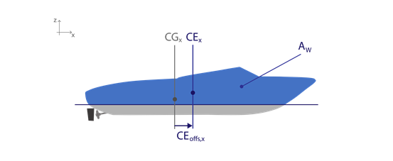
To adjust the tendency to turn, set the position of the wind center of effort. This is the point at which the overall wind force acts upon the ship. The location of this point is approximately the centroid of the surface Aw exposed to the wind. (see figure below)
When the wind center of effort CE is located away from the center of gravity CG of the ship towards the bow, the bow is blown away from the wind (leeward) If the center of effort is located towards the stern, the bow turns windwards.
With this parameter you set the longitudinal offset CEoffs,x of the center of effort relative to the center of gravity. Setting a positive value moves the center of the effort towards the bow.
2.15 Size of Lateral Plan
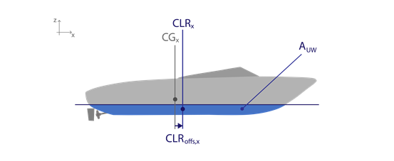
The lateral plan is the lateral projection of the underwater ship. This is the surface of the underwater ship you see when looking from the side. (see figure below)
The greater the area AUW of the lateral plan, the higher the ship will resist a lateral drift through the water.
The value is set relative to the ship default value. The default for a yacht with keel is much higher than for a motor boat.
2.16 Center of Lateral Resistance
When the ship is drifting sideways through the water, a resistance force acts on the ship underwater body. Analog to the wind center of effort, the center of lateral resistance is the point where the resistance force is applied. The center of lateral resistance is approximately at the centroid of the lateral plan.
If the center of lateral resistance CLR is not at the center of gravity CG, the sideways drift will also cause a moment of force that turns the bow of the ship.
You can set the longitudinal offset CLRoffs,x of the center of lateral resistance relative to the center of gravity. Setting a positive value will cause the bow to be pushed in the direction opposite to the drift.
Also the rudder surface contributes to the moment of force caused by the sideways drift. You change this contribution when you adjust the rudder size parameter.